UAS Radiometric Temperature Measurements
Radiometric Temperature Measurements
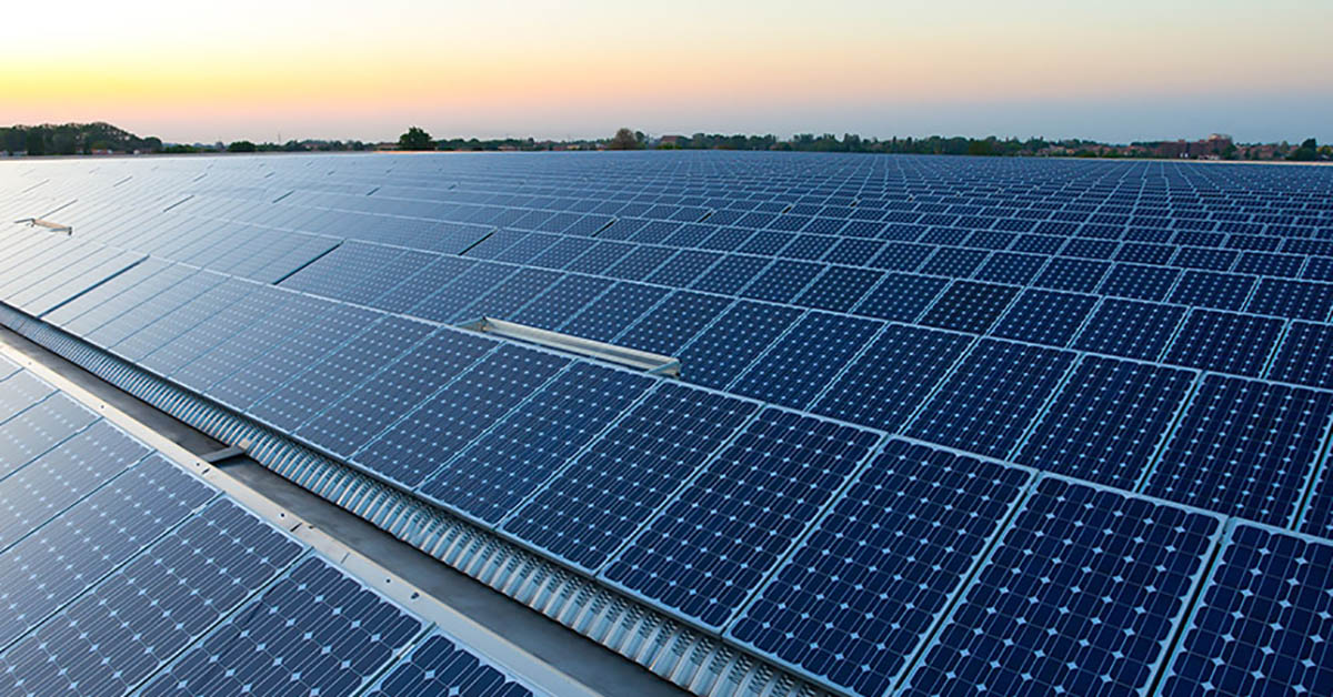
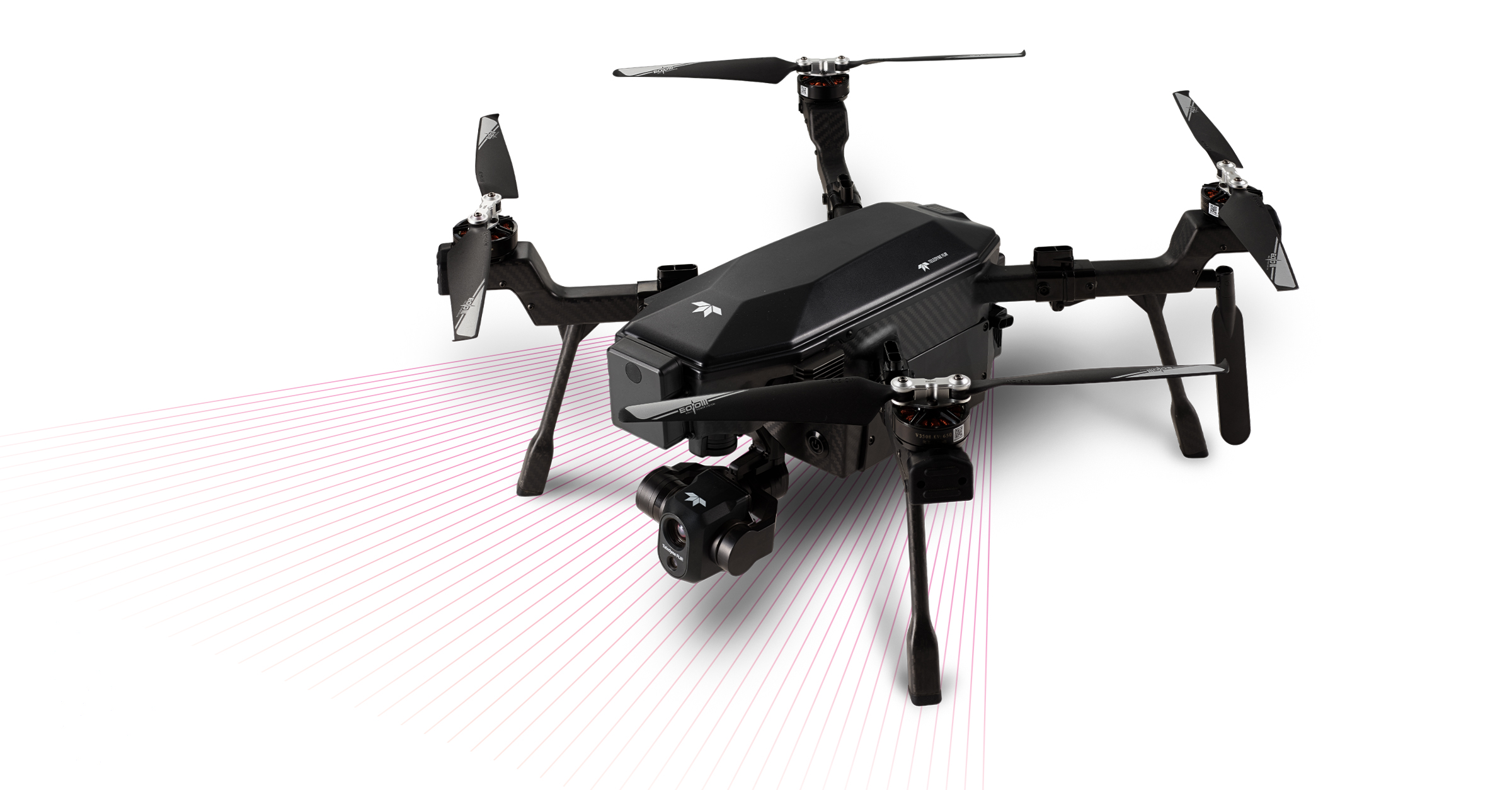
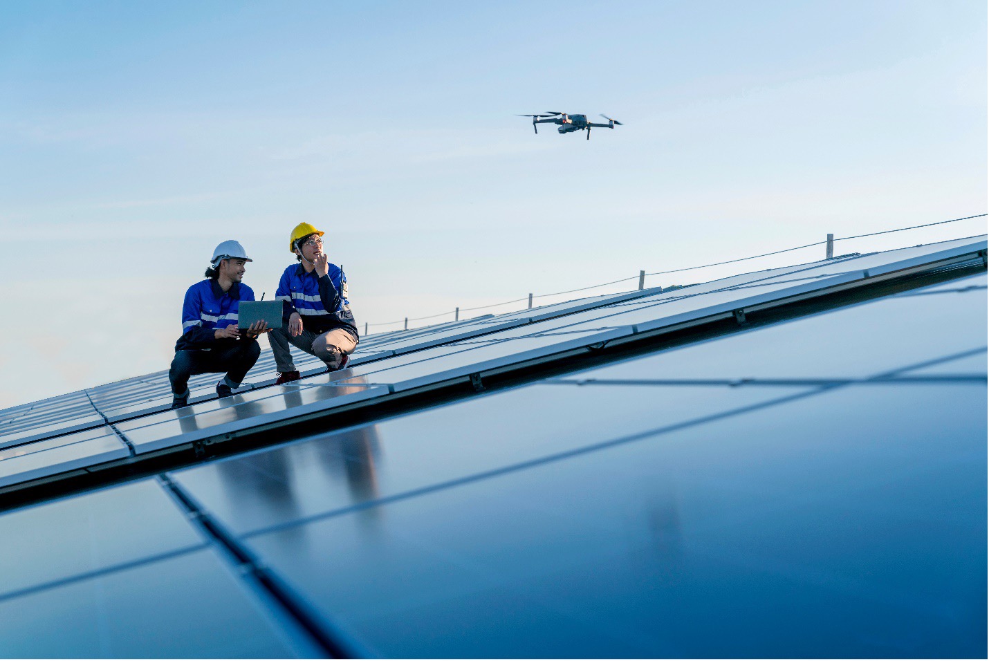
A radiometric thermal camera measures the temperature of a surface by interpreting the intensity of an infrared signal reaching the camera. This non-contact and non-destructive technique (NDT) gives users enormous advantages for many of their surface temperature measurement applications because it can be integrated into a FLIR Aerial package. This is sometimes referred to as a UAS or unmanned aerial system. A UAS allows an operator to move and position the thermal camera to quickly make temperature measurements over large areas and in difficult or dangerous environments. For example, a UAS can measure the surface temperature of a heat exchanger on a roof, a faulty connection on a high voltage transmission line, solar cells in a solar panel, and over large agricultural fields. However, the ability to remotely sense temperature, as opposed to direct surface contact, comes at the necessity to account for particular surface and environmental conditions; some of these conditions are illustrated as Figure 1.
It is important to distinguish radiometric temperature measurements as surface infrared measurements because radiometric measurements should be restricted to optically opaque materials. Metals and organic material are usually completely opaque and radiometric measurements should be able to resolve their surface temperature. Although there are materials that are semi-translucent to infrared heat (sapphire glass, zinc sulfide glass, zirconia oxides), radiometric measurements of these surfaces must account for the total volumetric and through-plane temperature of the material; this significantly increases the complexity of the analysis.
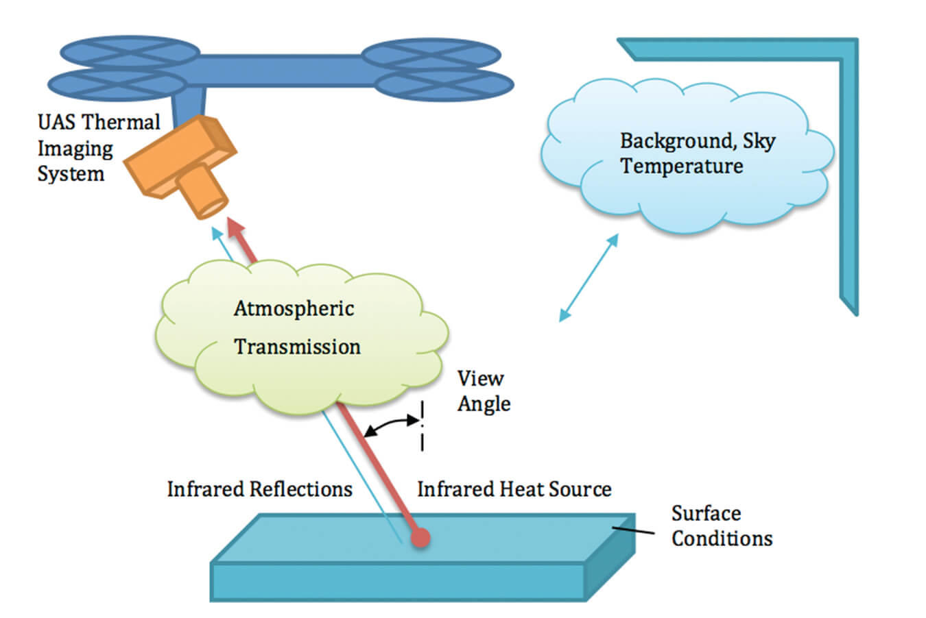
Remote temperature sensing of a surface relies on the ability to accurately compensate for surface characteristics, atmospheric interference, and the imaging system. The surface characteristics that influence the temperature measurement are surface emissivity and reflectivity at the infrared spectral wavelengths. The atmosphere will absorb and emit thermal energy based on its composition and the distance between the camera and the surface. Finally, the ability to spatially resolve detailed temperature measurements in a thermal image is influenced by image focus, blur, and pixel resolution. The influence of each of these factors on measurement accuracy is highly dependent on the specific measurement application and each must be accounted for and resolved.
Surface Characteristics
Emissivity
The emissivity is a measure of the efficiency of a surface to emit thermal energy relative to a perfect blackbody source, it directly scales the intensity of the thermal emission, and all real values are less than 1.0. The emissivity may be highly dependent on the surface morphology, roughness, oxidation, spectral wavelength, temperature and view angle. A measurement that does not account for the real emissivity of a surface will appear “colder” than it actually is. For agricultural applications, many organic materials and materials with very rough surfaces have emissivity values approaching unity. For other applications, including power line and solar cell inspection, the surface might be a highly polished glass or metal, both of which can have much lower emissivity values. As a reference, Table 1 demonstrates the wide range of emissivity values that may be encountered in UAS radiometric applications.
Reflectivity
A camera close to a surface is sensing both the heat sustained from the surface temperature and the reflected background environmental temperature. It is very challenging to make temperature measurements of a highly reflective surface because the image is influenced by the background thermal reflections. In a UAS application, an unpainted and clean metal roof can appear colder than it actually is because the shiny roof reflects the sky above it. Consider the case of a stainless steel sheet on a rooftop, 0.80 reflectivity and 0.20 emissivity, a radiometric temperature measurement would be highly biased towards the reflected background temperature of the sky. A clear sky may have a background temperature that is typically well below 0°C (32°F), and possibly as low as -20°C (-4°F). The actual sky background temperature will vary depending on atmospheric conditions and time of day.
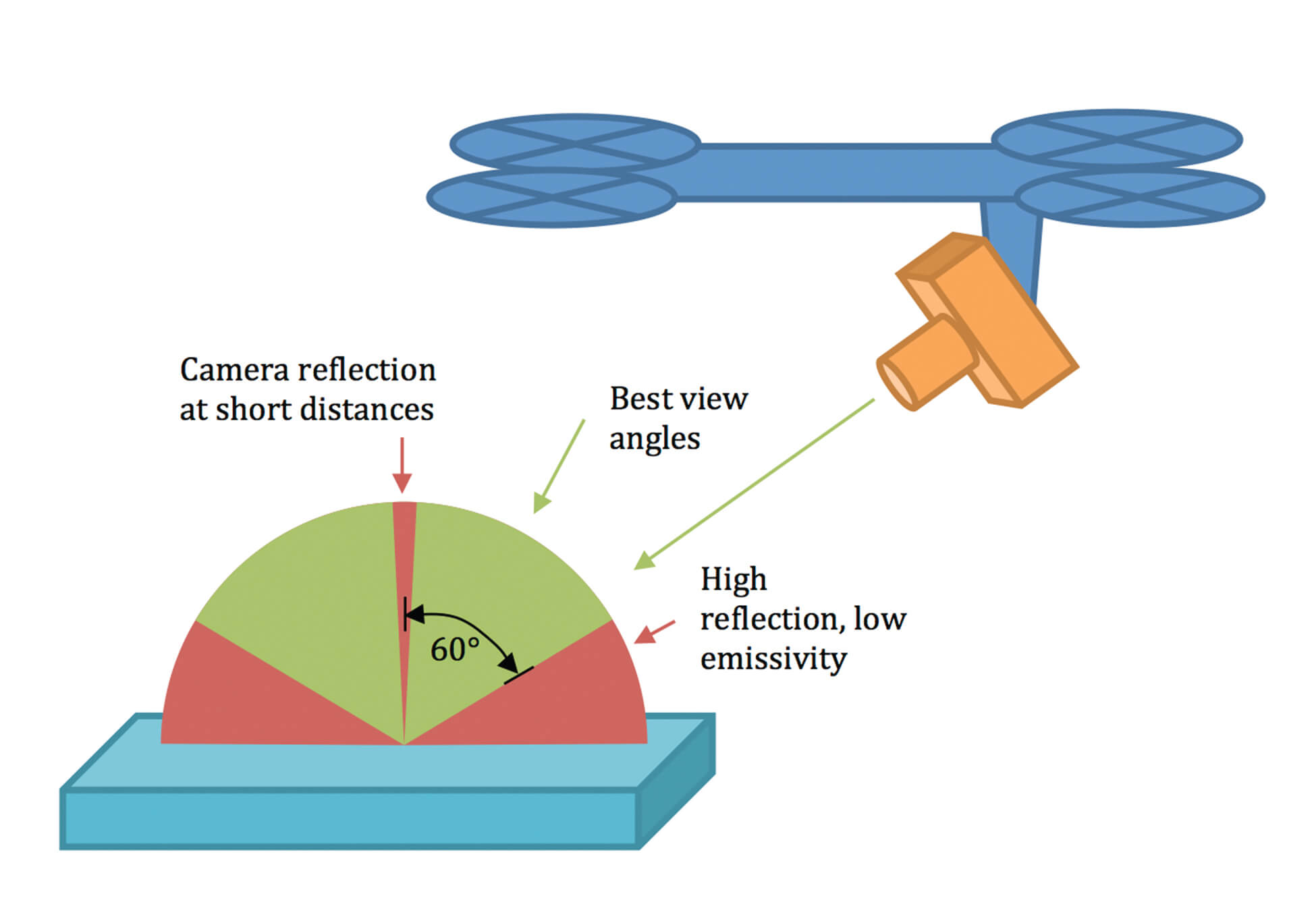
Reflective surfaces pose additional challenges in UAS applications; reflection of the sun in the thermal image will appear as sun glints and radiometric temperature measurements of the sun glints can be inaccurate by hundreds of degrees. It is advisable to take a sequence of images of the surface from different angles to reduce the influence of any single sun glint. However, care must be taken not make measurements at exceedingly oblique angles because reflectivity degrades based on view angle. Alternatively, a very close range and straight-on measurements can result in the camera viewing a reflection of itself and result in inaccurate measurements. Figure 2, illustrates the view angle challenges for radiometric temperature measurements and recommends making measurements less than 60° normal to the surface.
Much like emissivity, the reflectivity of a surface is highly dependent on the surface morphology and roughness. Since reflectivity (R) is related to emissivity (E) by R = 1-E , the importance of reflectivity can be greatly reduced by making measurements of surfaces with very high emissivity, ideally greater than 0.90. For UAS measurements of controlled surfaces, such as a steel tank on a rooftop, high emissivity/low reflectivity matte-flat black paint can be used to make “measurement patches” that result in highly reproducible measurements.
Atmospheric Transmission
The earth’s atmosphere interferes with the thermal image by absorbing and emitting infrared radiation based on the air density, relative humidity (RH), and distance between the object surface and the camera. The atmospheric transmission between the camera and the surface can change the radiometric temperature measurement and is a measure of the effective heat reaching the camera. Not accounting for the atmospheric transmission will result in radiometric measurements that appear colder than the actual surface temperature.
Consider a very warm and humid day, a 100 m (328ft) air path (35°C (95°F) air temperature, 80% RH) has a theoretical transmission of 80%. That means that only 80% of the thermal radiative heat emitted from surface will reach the camera. If this atmospheric transmission loss is not accounted for, then a UAS looking at a 50°C (122°F) object with a known emissivity of 0.97 will read 47.6°C (117..7°F): a 2.4°C (4.3°F) error caused by the air path alone! The best way to mitigate the atmospheric transmission effect is to minimize the distance between the UAS camera and the surface. For example, at 10 meters (32.8ft) the transmission is 96% and the radiometric temperature uncorrected for air path is 49.5°C (121.1°F).
The atmosphere can affect the temperature measurements in other unexpected ways. Measurements should always be performed in the absence of rain, snow, smoke, dust or any other obscurants because they too will reduce the atmospheric transmission and change the background temperature. Finally, remember that radiometric measurements only report the surface temperature and the surface temperature may be very sensitive to strong winds.
Temperature Spatial Resolution
A radiometric thermal image describing a surface provides a radiometric temperature measurement for each pixel. A very small surface in the image will become exceeding difficult to accurately measure as the number of pixels describing the dimensions of the surface is diminished. The spot-size effect is this degradation in measurement accuracy due to the effects of optical distortion, diffraction, stray light, and sensor image processing that result in a washed-out image. Not accounting for the spot-size effect will yield measurements that may be highly influenced by nearby surfaces. For example, a warm object may appear colder and a cold object may appear warmer than the actual temperatures.
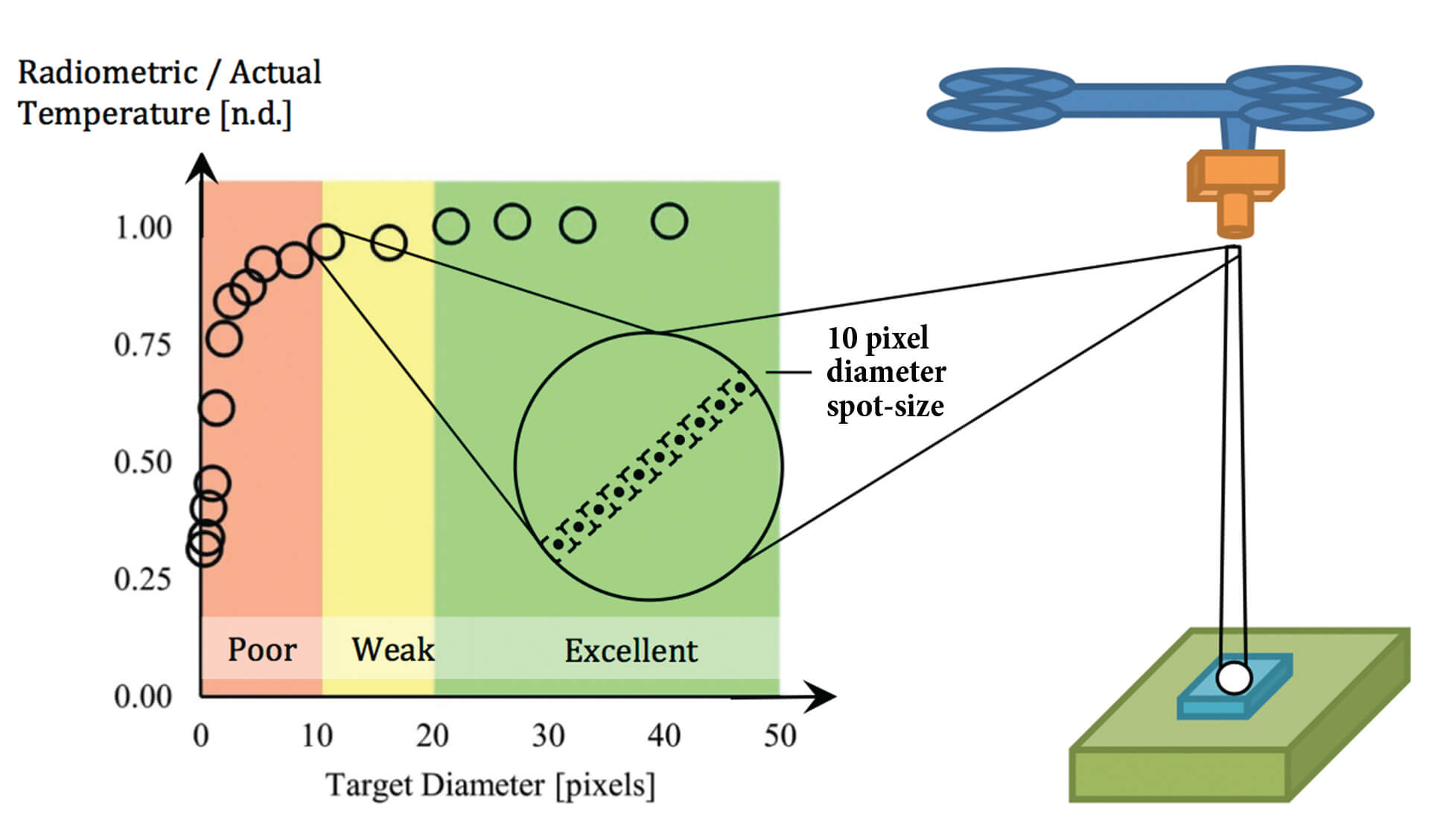
Although the spot-size effect may be highly dependent on the particular thermal camera, FLIR laboratory measurements on UAS cameras suggest that a measurement spot in the thermal image should be at least 10 pixels in diameter to report a meaningful measurement and a 20 pixel diameter is sufficiently large to negate the spot-size effect. Figure 3 illustrates the improvement in radiometric temperature accuracy as the spot-size is increased.
For UAS applications, the spot-size effect becomes increasingly relevant as the distance between the surface and the camera is increased and the number of pixels describing each spatial feature is reduced. The number of pixels used to resolve the surface area of an object is dependent on the pixel pitch, focal length, distance from the camera to the surface, and the smallest characteristic size (length, diameter) of the surface, Figure 4 illustrates these factors. The number of pixels (N) used to resolve an object is evaluated by the ratio of the camera angular subtense and pixel instantaneous field of view where, the surface to camera angular subtense α = d/s is the ratio of the distance between the camera to object surface (d) and the size of the object (s). The instantaneous field of view (IFOVp) of each camera pixel is calculated by taking the ratio of the pixel pitch (p) and focal length (f), IFOVp = p/f. These relationships can be manipulated to find the maximum recommended measurement distance, smallest necessary object size, and camera characteristics for any particular radiometric temperature application.
Consider a Thermal Radiometric camera with a 13mm lens, 640 by 512 pixel resolution sensor, 17 µm pixel pitch and that is at an altitude of 20 meters (65.6ft), a 30 cm (11.81in) square surface directly below the camera will only be 12 by 12 pixels in a thermal image.
The focus and blur of a thermal image can also increase the number of pixels necessary to make accurate radiometric measurements. For example, the shutter speed of the thermal camera is fairly long at 1/30 second and a rapidly moving UAS can result in a blurred image with reduced accuracy. A hot surface that is smeared out because of the motion of the UAS will look cooler and a cool surface may appear hotter. Gimbal mounts and active-stabilization techniques can be used to strategically reduce the jitter of the camera for maximizing camera stability and image focus.
Conclusions
In summary, these are a description of UAS factors that may influence the accuracy of radiometric surface temperature measurements. For surfaces with low emissivity and high reflection, straightening and oblique view angles should be avoided to reduce the impact of reflections and exacerbated oblique reflection. The surface emissivity should be high to reduce the impact of background temperature reflection and sun glints, ideally greater than 0.90. Alternatively, increasing the surface emissivity can be achieved by coupling a rough surface texture with high emissivity, and matte flat black paint to mitigate the impact of uncertain emissivity and high reflectivity.
The atmospheric transmission factors can be largely negated by making measurements to within 10 m (32.8ft) or less of the target surface and in a cool and clear atmospheric setting. These conditions mitigate the impact of air temperature, relative humidity, and air particulates. For longer distances, the atmospheric conditions (distance, humidity, temperature) will need to be well characterized to calculate the atmospheric transmission. Measurements greater than 10 meters are further impacted by the spot-size effect when the number of pixels describing any particular surface drops and the ability to make measurements of very small objects is severely impacted. Although it is important to make measurements with a spot-size diameter of at least 10 pixels, more pixels are necessary for blurred and out of focus images.
Related Articles
-
 Press Release
Teledyne FLIR debuts SIRAS Drone for Public Safety and Industrial Inspection
Read the story -
 Whitepaper
DELTA Solution Series - Part 3: Overhead Electrical Drone Inspections
Learn more -
 Whitepaper
DELTA Solutions Series - Part 4: Thermal Inspection of Solar Panels
Learn more